18Aug

Review elbow arrester voltage rating, MCOV, IEEE 386 interface, loop and radial placement, grounding and installation checks for MEE 2026.

Lightning and switching events can create short-duration overvoltages that travel through a distribution network towards cable ends, transformers and switchgear. Effective protection depends on where the surge is intercepted, the voltage at which the arrester operates and the insulation level of the equipment behind it.The 15/25/35-LEA elbow arrester combines a metal oxide varistor module with a rubber elbow for shielded deadfront applications. Its 15, 25 and 35 kV interface classes support pad-mounted transformers, entry cabinets, vaults and switching devices, but selecting the voltage-class label alone does not complete the protection design.

Map the surge path before choosing a catalogue number

A surge study begins with the network arrangement. Engineers should identify overhead-to-underground transitions, exposed cable sections, transformer terminals, switchgear interfaces, open points and radial ends. These locations influence where travelling-wave stress can appear and which assets sit inside the intended protection zone.The product is intended for installation at the end of a radial system and at both ends of an open point on a loop system. That guidance reflects two different network conditions. A radial end protects the termination of one supply path, while a normally open loop point has cable sections approaching from both directions.A distribution surge arrester should therefore be shown on the single-line diagram and equipment schedule, not added later as a generic accessory. The drawing should identify the bushing interface, system earthing and the equipment insulation being protected.

Separate voltage class from arrester voltage rating

A 15 kV elbow arrester interface can be supplied with several duty-cycle and maximum continuous operating voltage ratings. The same principle applies to the 25 kV elbow arrester and 35 kV elbow arrester ranges. This is why nominal system voltage cannot be used as the only selection field.The engineer should confirm nominal and maximum system voltage, phase-to-ground voltage and the neutral grounding arrangement. A four-wire multi-grounded wye system can lead to a different arrester rating from a low-impedance grounded, high-impedance grounded or delta system at a similar nominal voltage.MCOV is the voltage that the arrester can withstand continuously under specified conditions. The duty-cycle rating is another catalogue characteristic. Both must suit the system while maintaining an appropriate protective relationship with the cable, transformer or switchgear insulation. The current product table provides rating combinations for each interface class rather than one universal value.

Confirm the 200 A interface and deadfront arrangement

The 15/25/35-LEA range is associated with IEEE 386 standard 200 A loadbreak interfaces. The moulded insulating and semi-conducting rubber housing provides a shielded deadfront configuration when correctly installed and grounded. Compatibility should be confirmed across the bushing, insert and arrester rather than assumed from appearance.A loadbreak elbow arrester includes an operating eye and probe arrangement for the compatible interface. Its presence does not authorise unplanned live work. Installation and maintenance instructions require associated equipment to be de-energised and the work to be performed by qualified technical personnel using the specified procedures and protective equipment.For a cable elbow arrester application, the submittal should state interface class, duty-cycle rating, MCOV, system grounding, equipment location and the exact catalogue number. This provides a reviewable connection between the protection study and the item procured for site.

Keep grounding inside the protection design

The varistor diverts surge current towards earth, so the grounding path is part of arrester performance. Installation instructions require the ground lead to be connected to the system earth and the grounded end to face down. A missing, loose or unsuitable connection can compromise the intended protection and create a serious safety risk.The grounding arrangement should be coordinated with the transformer or switchgear design, cable shield bonding and the site's earthing system. Route length, connection quality and mechanical protection of the lead should be resolved in the installation detail rather than left to field interpretation.This is particularly relevant when specifying a lightning arrester for distribution transformer installations. The arrester, transformer interface and earth connection need to function as one protection zone. A device installed in the correct cabinet but connected poorly to earth does not fulfil the design intent.

Turn installation details into acceptance checks

Before installation, the interface should be clean, dry and in good condition. The instructions call for even application of silicone lubricant to the inner interface without excess, followed by firm engagement with the compatible bushing. Where an indicating ring is present, correct seating is confirmed when the ring is covered.The inspection record should capture the equipment reference, arrester catalogue number, interface, grounding connection and installation status. Photographs can help confirm orientation and seating, while the energisation checklist should verify that the approved system rating matches the installed item. These checks are particularly relevant when coordinating Switchgear and power solutions MEE Dubai projects.Later inspection of an mv elbow arrester should cover physical condition, contamination, evidence of overheating or discharge, secure grounding and any change to the network arrangement. If a loop point, transformer connection or grounding method changes, the original protection study should be reviewed rather than relying on the existing hardware automatically.

Review the protection zone at Middle East Energy 2026

Middle East Energy 2026 takes place from 1 to 3 September at Dubai World Trade Centre, UAE. Utility engineers, consultants, contractors and procurement teams can use the event to compare surge-protection selections against actual distribution layouts.Dutco Tennant will feature the 15/25/35 kV elbow surge arrester at Hall H5, Stand D10. Visitors can make the discussion more useful by bringing the nominal and maximum system voltage, grounding arrangement, single-line diagram, bushing interface and target equipment insulation data, with support from an Electrical Connectors Supplier in MEE 2026.A lightning arrester elbow protects effectively when its rating, interface, grounding and location are coordinated with the network. Treating those inputs as one design decision helps reduce exposure to lightning and switching surges while giving installation teams a clear, verifiable scope and supporting coordination with a Transmission Equipment Supplier in MEE Dubai.elbow arrester

Wooden Poles are often preferred in various utility applications because they are derived from renewable natural resources and can support environmentally responsible infrastructure development when sourced and treated properly

As utility infrastructure continues to evolve, the demand for reliable, durable, and environmentally responsible network components is increasing across power distribution, telecommunications, and smart city developments. Modern utility projects are no longer focused only on operational performance sustainability, lifecycle efficiency, and environmental impact are now equally important considerations.Across urban and rural infrastructure projects, Electrical distribution poles remain an essential part of power and communication networks. They support overhead utility systems, enable reliable energy transmission, and help connect expanding communities and industrial developments.With growing emphasis on sustainable infrastructure, many utility operators and project developers are increasingly adopting natural and renewable pole solutions that combine operational reliability with long-term environmental benefits.

The Growing Need for Sustainable Utility Infrastructure

Modern energy and communication networks are expanding rapidly due to increasing urbanization, smart city development, and rising energy demand. At the same time, governments and infrastructure planners are placing greater importance on environmentally conscious construction practices.Utility infrastructure today is expected to support:·    Long operational life·    Reliable network performance·    Sustainable material usage·    Reduced environmental impact·    Lower maintenance requirements·    Cost-efficient deploymentAs infrastructure projects continue to grow, sustainable utility materials are becoming an important part of future-ready network planning.

Supporting Expanding Power Distribution Networks

Reliable pole infrastructure is critical for maintaining stable electrical distribution across residential communities, industrial zones, transportation systems, and rural development projects. Power distribution systems often operate in demanding environmental conditions where durability and structural reliability are essential for long-term network stability.Modern utility pole systems are commonly used for:·    Electrical transmission lines·    Rural electrification projects·    Street lighting infrastructure·    Utility expansion networks·    Smart grid development·    Communication line supportStrong and dependable pole infrastructure helps utility operators maintain efficient energy distribution while supporting growing network demands.

Natural Materials Supporting Sustainable Development

Sustainability is becoming increasingly important in utility infrastructure planning. Renewable construction materials are now being considered more frequently for projects focused on reducing environmental impact and supporting long-term resource efficiency.Wooden Poles are often preferred in various utility applications because they are derived from renewable natural resources and can support environmentally responsible infrastructure development when sourced and treated properly.Compared to some conventional alternatives, natural pole solutions may offer benefits such as:·    Lower environmental impact·    Reduced manufacturing energy requirements·    Easier transportation and handling·    Sustainable lifecycle potential·    Efficient installation processesAs utility sectors continue moving toward greener infrastructure strategies, renewable material solutions are gaining wider acceptance across global projects.


Supporting Smart Utility and Communication Networks

Modern infrastructure is increasingly connected through digital communication systems, smart monitoring technologies, and automated utility management platforms.Pole infrastructure today supports much more than basic power transmission. Utility networks now require support for:·    Smart grid systems·    Fiber optic communication·    Remote monitoring equipment·    Public lighting systems·    IoT infrastructure·    Telecommunications networksReliable pole systems help create the physical backbone required for modern smart utility environments.Organizations implementing utility pole solutions from Dutco Tennant LLC often prioritize long-term durability, operational reliability, and sustainable infrastructure performance for utility and communication projects.

Efficient Installation and Field Adaptability

Infrastructure projects often involve challenging site conditions, remote locations, and large-scale deployment requirements. Utility components that are easier to transport and install can significantly improve project execution efficiency.Natural pole systems are widely used in projects requiring:·    Rural infrastructure expansion·    Fast deployment timelines·    Flexible installation conditions·    Utility network extensions·    Remote access installationsTheir adaptability makes them suitable for both urban and remote infrastructure applications where operational practicality is important.As utility expansion projects continue to increase globally, efficient installation processes are becoming a major consideration for project developers and contractors

Long-Term Reliability in Utility Applications

Utility infrastructure is expected to operate continuously for many years while withstanding changing weather conditions, environmental exposure, and operational demands.Properly engineered and treated pole systems are designed to support long-term performance across:·    Power distribution environments·    Telecommunications infrastructure·    Outdoor utility networks·    Public infrastructure systemsDurable infrastructure materials help utility operators reduce maintenance frequency and improve overall network stability.Long operational life is particularly important for utility projects where replacement and maintenance activities may affect service continuity and operational efficiency

Supporting Rural and Urban Infrastructure Growth

As cities expand and rural electrification projects continue to develop, reliable utility infrastructure remains essential for supporting social and economic growth.Pole infrastructure continues to play a major role in:·    Expanding access to electricity·    Supporting communication connectivity·    Enabling smart infrastructure deployment·    Improving public utility access·    Strengthening regional developmentThe ability to support both power and communication systems makes utility poles an important component of modern infrastructure planning

A Sustainable Approach to Future Utility Networks

Infrastructure developers today are increasingly focused on balancing operational performance with sustainability objectives. Renewable materials, efficient construction practices, and long-term infrastructure durability are becoming central considerations in utility planning.As smart utility systems continue to evolve, sustainable pole solutions are helping support reliable energy distribution and communication infrastructure while aligning with modern environmental and operational goals.Reliable utility infrastructure is not only about network performance anymore, it is also about creating efficient, durable, and environmentally responsible systems capable of supporting the growing demands of future cities, industries, and connected communities.

24Apr

The PRO Round Bollard is designed with a diffused optical system that provides even distribution without harsh cutoff, making it suitable for applications where visual comfort matters as much as lux levels

Pathway lighting is one of those design elements that looks straightforward on paper but frequently causes problems during and after installation. Specifying the wrong bollard height or miscalculating spacing intervals leads to either overlapping pools of light or dark gaps that defeat the purpose of the installation entirely. For engineers and project contractors working on landscaped walkways, commercial campuses, or public infrastructure, getting these parameters right from the start saves significant rework cost.

A Small Miscalculation With a Large Price Tag

The core challenge with outdoor bollard lighting is balancing aesthetics with photometric performance. A bollard that is too short may produce glare at eye level without delivering adequate ground coverage. One that is too tall shifts the light distribution pattern in ways that create uneven illumination, bright spots near each unit and dim zones in between. Pathway projects that ignore spacing calculations often end up with lux levels that fall short of safety standards, particularly in areas with pedestrian traffic after dark. The result is not just a visual problem; inadequate pathway lighting can expose project owners to liability and trigger compliance failures on handover.

Height and Spacing: Two Numbers That Need to Work Together

Selecting the appropriate bollard height and spacing requires understanding the photometric output of the specific luminaire and matching it to the pathway width and surface reflectance. For most pedestrian walkways, round bollard lights in the 600mm to 1000mm height range work well they keep the light source below direct sightlines while directing illumination downward and outward across the path surface. The PRO Round Bollard, for instance, is designed with a diffused optical system that provides even distribution without harsh cutoff, making it suitable for applications where visual comfort matters as much as lux levels.Spacing is typically calculated at 2.5 to 4 times the mounting height, depending on the required average illuminance and the luminaire's beam angle. A 900mm bollard on a 2-metre-wide pathway might be spaced at 3 to 3.5 metres to achieve consistent coverage. Procurement teams should request IES or LDT photometric files from the manufacturer and run a DIALux or AGi32 simulation before finalising quantities, this prevents over-ordering and ensures the design meets the project's lighting brief.


What Happens When the Simulation Gets Skipped

A landscape contractor working on a mixed-use residential development in the UAE specified pathway bollard lights at 1-metre intervals based on a visual estimate rather than a photometric model. After installation, the client flagged unacceptable dark zones between units along a 200-metre walkway. Replacing the luminaires with outdoor bollard lighting at a calculated spacing of 3.2 metres using a round bollard with a wider beam distribution resolved the uniformity issue and reduced the total fixture count by nearly 40%, cutting both material and installation costs.

Before the Purchase Order Goes Out

Before procurement, engineering teams should confirm that the bollard specification includes IP rating (IP65 minimum for exposed outdoor installations), material compatibility with the local environment particularly in coastal or high-humidity conditions where corrosion resistance matters and photometric data in a standard format for simulation. Verifying IK ratings for impact resistance is also relevant in public-access areas. Lead times for architectural lighting products can vary significantly depending on finish and configuration, so confirming stock availability or production lead times early in the project timeline avoids delays at the fit-out stage.

A Note on Regional Suppliers

Suppliers active in the GCC construction and infrastructure space, such as Dutco Tennant which carries a broad catalogue of industrial and construction products across the region are among the distributors procurement teams reference when sourcing outdoor bollard lighting for large-scale projects.


Specify First, Procure Second

Pathway bollard lighting performs best when height and spacing are determined by photometric data rather than estimation. The difference between a well-specified installation and a poorly lit one often comes down to a simulation run before procurement. Contractors and specifiers working on upcoming pathway projects would do well to revisit their lighting calculations early ideally before quantities are locked in.

Discover how bridge bearings & expansion joints keep large-scale infrastructures sturdy & resilient. Dive into their fascinating role!

expansion joint

Have you ever marvelled at the sight of a grand bridge stretching across a vast river or connecting two distant points over land? Bridges are not just marvels of engineering; they're lifelines, connecting communities and facilitating commerce.

But have you ever wondered what keeps these massive structures sturdy and resilient against the forces of nature and wear and tear? Enter the unsung heroes of bridge construction: bridge bearings and expansion joints.

What Are Bridge Bearings?

Imagine a bridge as a colossal, immovable giant. Now, picture it being able to sway, shift, and adjust with the elements. That's where bridge bearings come into play.

These components, often made of steel, rubber, or a combination of materials, serve as the interface between the bridge superstructure (the part supporting the traffic) and the substructure (the foundation).

Bridge bearings allow controlled movement, enabling the bridge to expand, contract, and rotate slightly in response to temperature changes, traffic loads, and seismic activity. Without these bearings, the bridge would be prone to cracking, buckling, or even collapsing under stress.

Types of Bridge Bearings

There's no one-size-fits-all solution when it comes to bridge bearings. Engineers select the type of bearing based on factors like bridge design, location, expected traffic loads, and environmental conditions. Some common types include:

Fixed Bearings: These bearings restrict movement in all directions, providing vertical support while allowing minimal horizontal movement.

Sliding Bearings: As the name suggests, these bearings allow horizontal movement, typically along a smooth surface, to accommodate thermal expansion and contraction.

Roller Bearings: These bearings allow both vertical and horizontal movement by incorporating rollers, reducing friction and distributing loads more evenly.

Pot Bearings: A type of sliding bearing, pot bearings consist of a concave pot and a convex disc, allowing movement in multiple directions while providing vertical support.

The Role of Expansion Joints

Now, let's talk about expansion joints, the flexible connectors between adjacent spans or sections of a bridge. Just like bridge bearings, expansion joints accommodate movement caused by temperature changes, seismic activity, and traffic loads.

However, expansion joints focus on managing movement at specific points rather than supporting the entire structure.

Expansion joints come in various forms, including modular joints, strip seals, and finger joints. Each type offers unique benefits in terms of durability, ease of installation, and maintenance requirements.

By allowing controlled movement, expansion joints help prevent the accumulation of stress within the bridge structure, prolonging its lifespan and ensuring passenger safety.

The Importance of Maintenance

While bridge bearings and expansion joints play crucial roles in ensuring the integrity of large-scale infrastructures, their effectiveness relies heavily on regular maintenance and inspections. Over time, these components can deteriorate due to exposure to environmental factors, heavy traffic, and general wear and tear.

Routine inspections allow engineers to detect signs of damage or malfunction early on, enabling timely repairs or replacements to prevent catastrophic failures.

End Thoughts

Bridge bearings and expansion joints may not be the most glamorous elements of bridge construction, but they are undeniably vital. By facilitating controlled movement and accommodating various forces, these components contribute to the strength, durability, and safety of large-scale infrastructures.

Starting on a bridge construction project soon? Selecting the right partner from a plethora of bridge expansion joint distributors is crucial for project success. Dutco Tennant LLC is a trusted name that can supply not just high-quality expansion joints but premium bridge bearings as well. Connect with them to discuss your project prospect.

Get to know why partial discharge monitoring is important. Discover more on PD monitoring at MEE 2024 Exhibition. Visit Dutco Tennant’s showcase to learn more.

Monitoring Partial Discharge

Electricity is a crucial part of our life, while we may not spare time to ponder on that thought, it certainly plays a critical role in our lives. With that being said, even a few minutes of interruption or worse power outage can result in hefty loss.No utility company wants to endure that. This is why, when it comes to the world of electrical engineering, ensuring efficiency and safety of equipment is paramount. One of the crucial aspects of it that often goes under the radar however it deserves much attention is partial discharge monitoring in insulated electrical assets.In this blog, we will focus on why monitoring of partial discharge in electrical equipment should matter. Read on to learn about its importance.

What is Partial Discharge?

Before we even begin to decipher the importance of partial discharge, let us understand what is actually partial discharge. In layman terms, it can be described as a miniscule spark that occurs within the insulation material of the electrical equipment.While this tiny activity feels harmless initially, not paying attention can quickly lead to failure risks in insulated electrical equipment. In fact, PD can be traced to be one of the primary root causes behind failures in such equipment.

What Triggers Partial Discharge Activity?

Now, you may wonder what exactly triggers PD activity in the first place? Here’s a breakdown -The insulated material of electrical equipment acts as a protective element that safeguards the conductive parts from unwanted interactions. But there are many factors that impact this material and make insulation imperfect. These factors include impurities in the material, ageing, mechanical stress, etc.When voltage is applied, these imperfections transform into hotspots ultimately triggering PD events. While PD activity may look small, it can definitely weaken the entire structure.

Reasons Why PD Monitoring Becomes Important

Monitoring of partial discharge becomes more than necessary. Some of the compelling reasons are –

Catastrophic Failure Prevention: PD activity might trigger with small impact but if left unchecked it can quickly be the reason behind causing major issues. Regular monitoring, especially real-time data can help catch these early signs before any escalations. Therefore, preventing the situation from turning into catastrophic failures.Ensures Reliability: Sudden failure equipment only happens due to lack of proper PD monitoring. Failure risks during extreme weather conditions only doubles when PD activity is not tracked. With consistent PD monitoring, you can ensure your equipment’s reliability throughout its service.

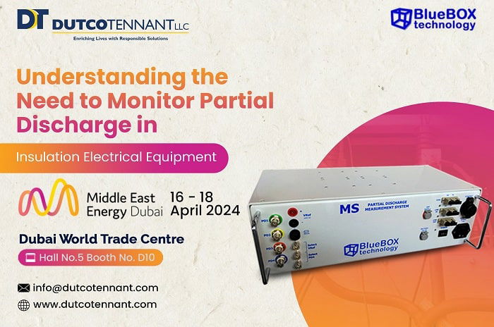
Prolonged Equipment Lifespan: PD monitoring at regular intervals helps to keep your equipments’ health in check. This means you extend their lifespan which helps in reducing maintenance and repair costs.The Middle East Energy Exhibition 2024 is approaching fast and one of the exhibitors of the event, Dutco Tennant will feature a cable partial discharge monitoring system. This product is by their partner Ampacimon and part of their patented solution – BlueBOX Technology.

The system is capable of tracking online PD activity consistently producing real-time data that enhances the monitoring process. Make your way to their Booth D10, Hall 5 from 16-18 April in Dubai World Trade Centre where you can meet the partner and discuss more on partial discharge and their solution to control its triggers.

I BUILT MY SITE FOR FREE USING